Basic Symbols Used In Technical Drawing Basic types of symbols used in engineering drawings are countersink counterbore spotface depth radius and diameter Here are more commonly used engineering drawing symbols and design elements as below
This document introduces the 11 main line types used in technical drawings visible hidden center dimension extension leader section cutting plane phantom viewing plane and break lines Drafting Symbols Symbols provide a common language for drafters all over the world However symbols can be meaningful only if they are created according to the relevant standards or conventions This document describes and illustrates common dimensioning GD T architectural piping and electrical symbols Standard Dimensioning Symbols
Basic Symbols Used In Technical Drawing
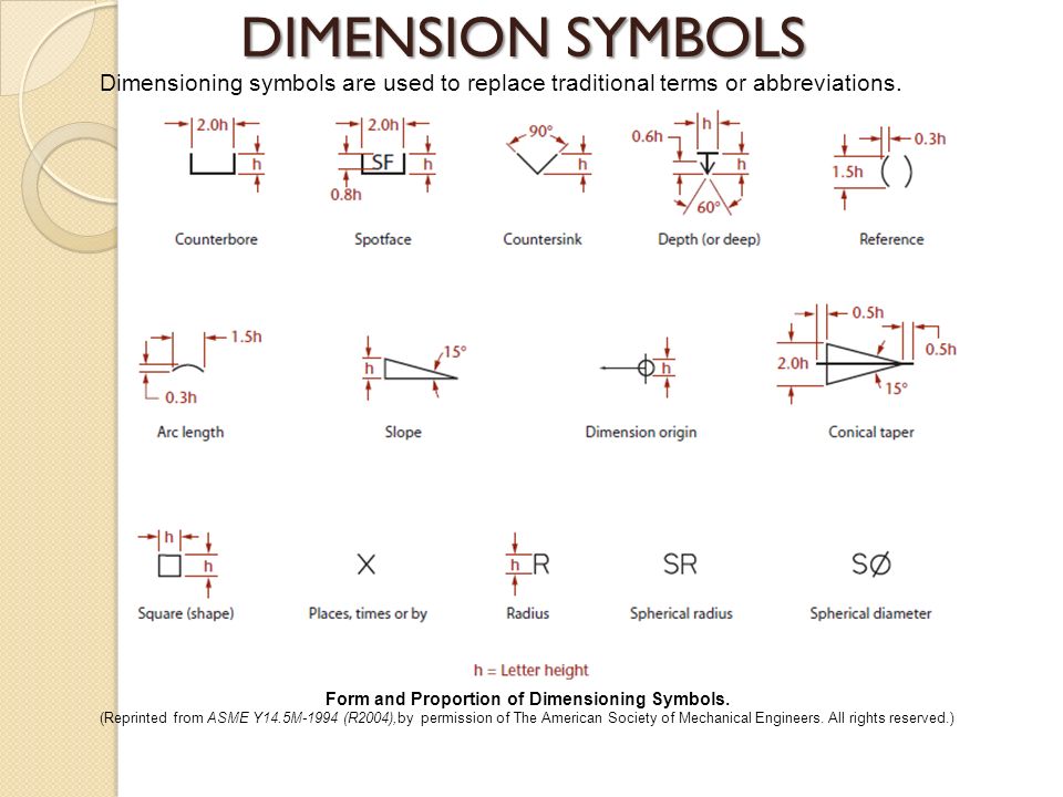
Basic Symbols Used In Technical Drawing
https://paintingvalley.com/drawings/drawing-dimension-symbols-13.jpg
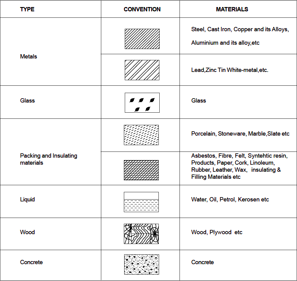
Conventions ENGINEERING DRAWING
https://www.educationalstuffs.in/wp-content/uploads/2022/01/conventions.png

How To Read Mechanical Engineering Drawing Symbols Wiring Work
https://i0.wp.com/blogger.googleusercontent.com/img/b/R29vZ2xl/AVvXsEicqzyMToS5vjnduKPMqaTpuAbmKhE8sLZyKEAOkOpudVG-eVr0wiweASilvrlcdCD6m_eAFSIlZOhM4nqEhJPSC02byxI6ixh3b7FEj-C4oQppIzjVM4IFSLXk2GGkoE-LOno7ushCtjtE7SvodL-3uKndB8gpwM8WI1irXqIEdKB6kdLUSFqK77KD/s16000/mechanical-engineering-drawing-symbols-gd&t-symbols-2.png?strip=all
In engineering drawings symbols are graphical representations of specific features instructions or components Key types of symbols are dimension symbols representing measurements feature symbols surface roughness contours etc and material symbols indicating the type of material used Symbols used in the technical drawing and engineering drawing Symbols used according to the the ASTM standard and ISO standard
Engineering drawing symbols are graphical representations used in technical drawings to specify key features such as material type dimension tolerances or machining processes These symbols help standardize information so that everyone involved in the This guide offers a comprehensive overview of the most common symbols used in technical drawings spanning multiple disciplines including mechanical electrical and architectural engineering
More picture related to Basic Symbols Used In Technical Drawing
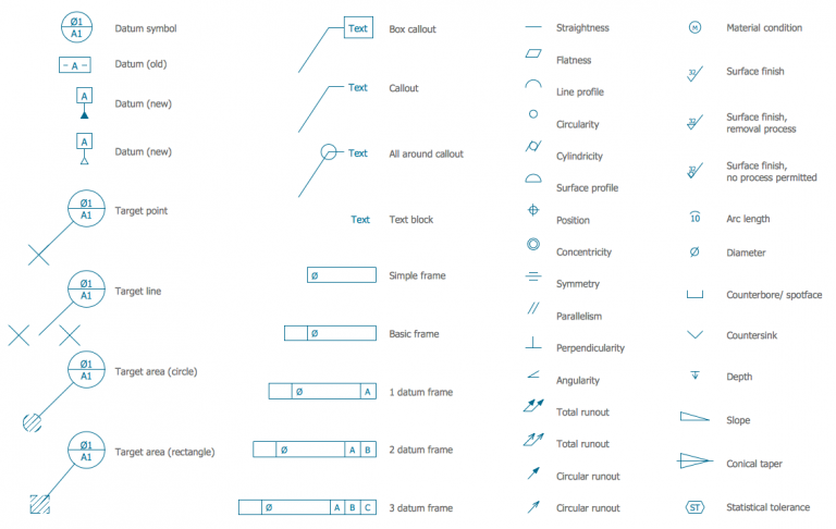
Standard Engineering Drawing Symbols
https://www.cnclathing.com/wp-content/uploads/engineering-drawing-symbol-768x486.png
Technical Drawing Symbols
https://www.coursehero.com/qa/attachment/20165759/

Simbologia De Desenho Tecnico REVOEDUCA
https://www.engproguides.com/images/machinebasic-1.jpg
The basic symbol types used in engineering drawings are diameter depth radius counterbore spotface and countersink The following are commonly used engineering drawing symbols and design elements Discover the essential symbols used in engineering drawings with our comprehensive guide Learn how to interpret these crucial elements to enhance your understanding and accuracy in technical drawings
[desc-10] [desc-11]
Design Symbols In Mechanical Engineering
https://lh3.googleusercontent.com/proxy/KdD079Pprj4tKMZ7PaO--3O_s3_YvblOzJR0yfn3aUG_6iaxeYV9UknE546d8cU0YDanNkMlt9oqkmOQ5gI2NV-Xets9Ms76zSIjtZdS9mxzAsjXyTIT6CcSc0EcT8zm2Ga6F0Y2_BlwLOVOKsM--zTCZzj9=s0-d

Engineering Block Diagram Symbols Symbols Mechanical Drawing
https://i.pinimg.com/736x/d8/a8/ef/d8a8ef271c679b87906a9d31cf5d889f.jpg
https://www.cnclathing.com › guide › engineering...
Basic types of symbols used in engineering drawings are countersink counterbore spotface depth radius and diameter Here are more commonly used engineering drawing symbols and design elements as below
https://www.slideshare.net › slideshow
This document introduces the 11 main line types used in technical drawings visible hidden center dimension extension leader section cutting plane phantom viewing plane and break lines

Mechanical Schematic Drawing Symbols Symbols Dwg
Design Symbols In Mechanical Engineering

Technical Drawing Symbols

Engineering Drawing Symbols And Their Meanings Pdf At PaintingValley
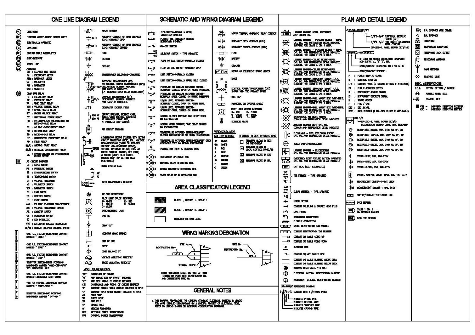
Engineering Drawing Symbols And Their Meanings Pdf At PaintingValley

Engineering Schematics Wotlk Wow Classic Wotlk Engineering G

Engineering Schematics Wotlk Wow Classic Wotlk Engineering G

List Of Engineering Drawing Symbols Drawing Word Searches
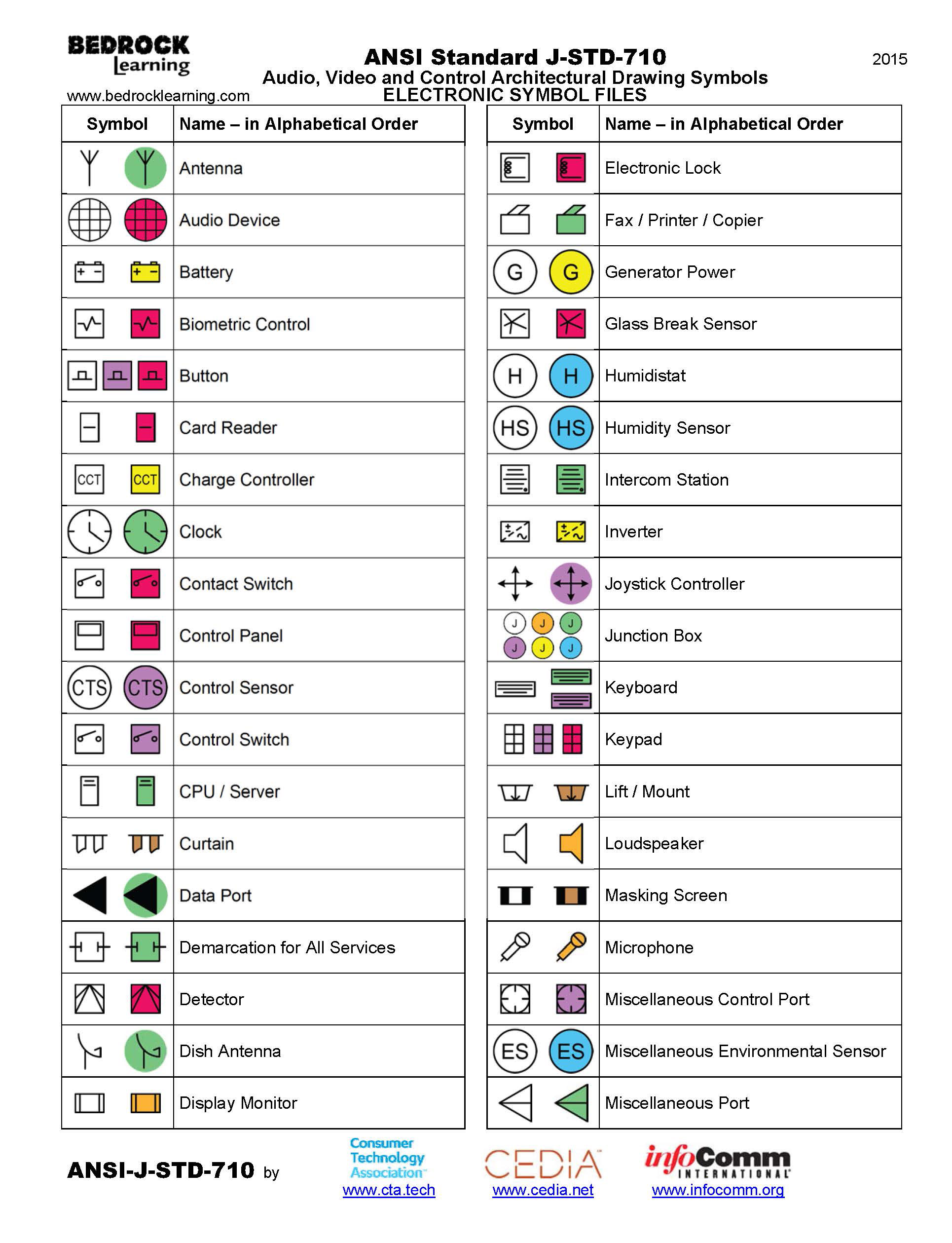
Architectural Electrical Schematic Symbols

Common Symbols In Engineering Drawings
Basic Symbols Used In Technical Drawing - [desc-12]