Block And Schematic Diagrams Definition A block and schematic diagram is a pictorial representation of a system or process that is used to help electrical engineers design and explain circuits and systems Block diagrams show the components and connections
The main difference between a block diagram and a schematic diagram is the level of detail provided A block diagram focuses on the overall structure and relationships between components while a schematic diagram provides a Block and schematic diagrams are two of the most common types of diagrams used to map out a circuit s components and connections according to best practices A block
Block And Schematic Diagrams Definition
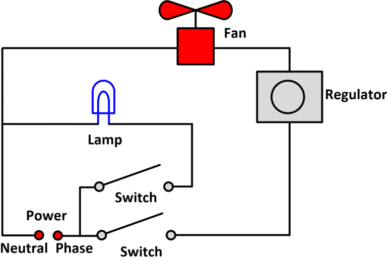
Block And Schematic Diagrams Definition
https://electricala2z.com/wp-content/uploads/2018/09/fan-768x518.gif

Reading A Circuit Diagram
https://cdn.sparkfun.com/r/600-600/assets/6/8/6/d/1/51cdc767ce395f7558000002.png

Block Diagram Symbols
https://www.researchgate.net/profile/Hiroaki_Kitano2/publication/228951634/figure/fig10/AS:300742675058691@1448714049213/A-symbol-set-for-the-block-diagram.png
Schematic diagrams show detailed drawings and information of the individual parts that a system or machine consist of and how they interact Block diagrams describe a system Block and schematic diagrams are visual representations of systems or processes that use blocks and symbols to convey information They are commonly used in engineering architecture
A block diagram is a diagram of a system in which the principal parts or functions are represented by blocks connected by lines that show the relationships of the blocks 1 They are heavily used in engineering in hardware design Block Diagram A block diagram is a type of electrical drawings that represents the principle components of a complex system in the form of blocks interconnected by lines that represent their relation It is the simplest form of
More picture related to Block And Schematic Diagrams Definition
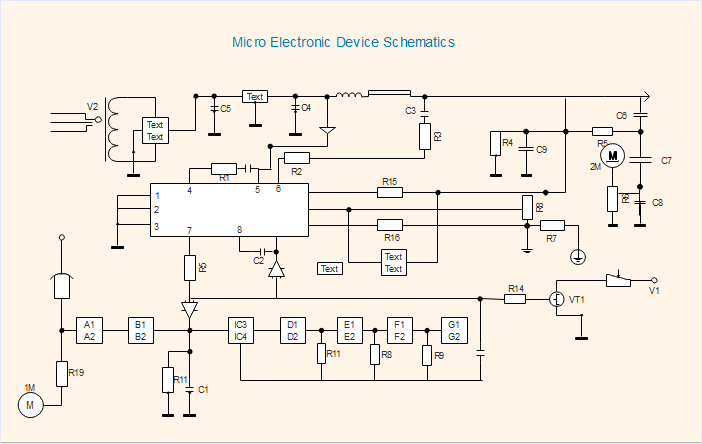
1 20 2 Schematics
https://www.edrawsoft.com/circuitdiagram/images/micro-electronic-device-schematics.png

Schematic Diagrams And Circuits
https://cdn.sparkfun.com/assets/6/8/6/d/1/51cdc767ce395f7558000002.png
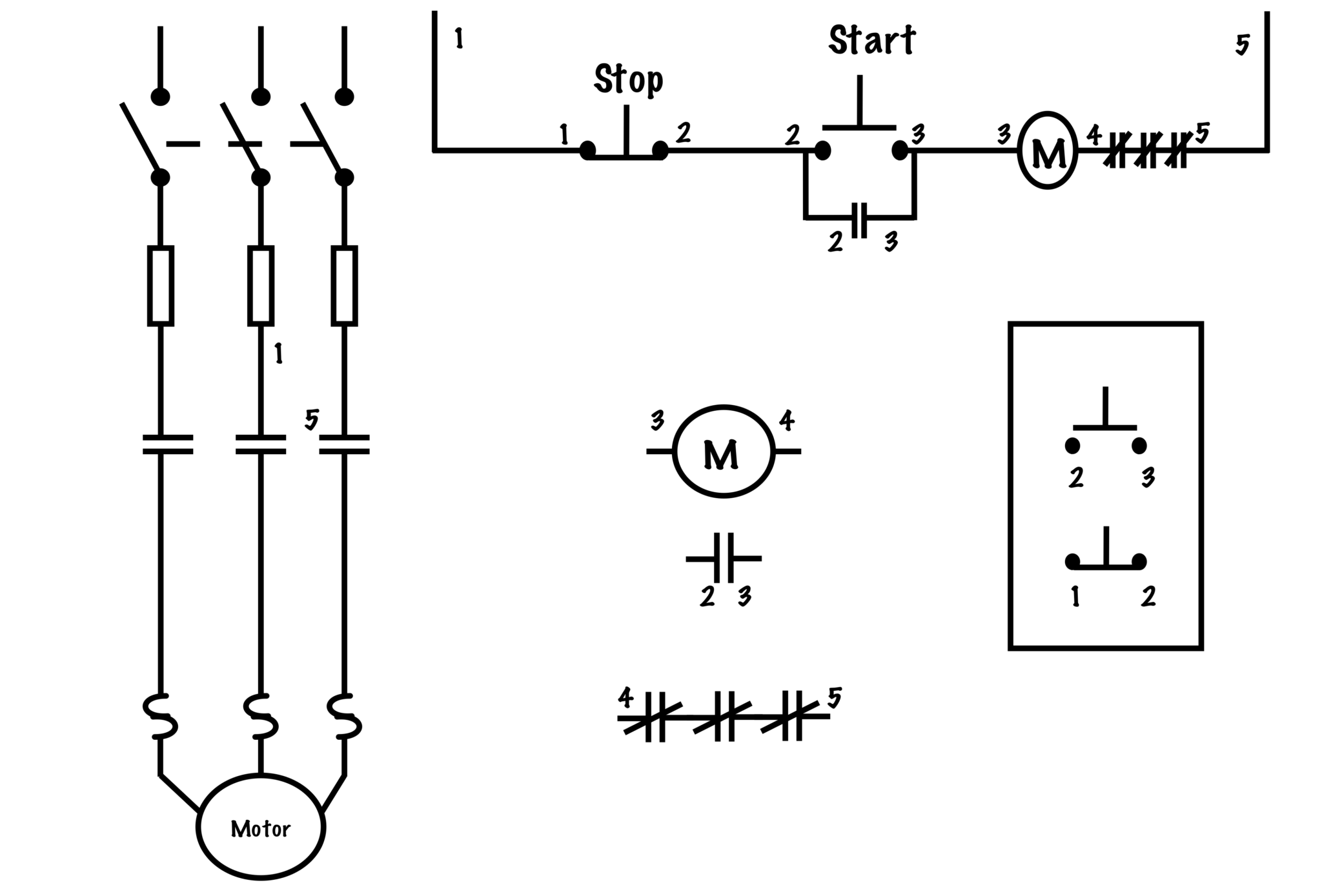
Schematic Diagram Electrical Circuit
https://opentextbc.ca/basicmotorcontrol/wp-content/uploads/sites/314/2020/08/Wiring-V-Schematic-2-2-e1579627986698-2048x1389.png
Schematic diagrams are used for representing the overall arrangement and functioning of a system usually made up of components On the other hand block diagrams are typically used for visualizing the flow of A block diagram is a high level drawing of a system A schematic shows the details A block diagram for instance of a superhetrodyne radio receiver as is commonly
A schematic diagram is a fundamental two dimensional circuit representation showing the functionality and connectivity between different electrical components It is vital for a PCB designer to get familiarized with the A block diagram shows a higher level or organizational layout of functional units in a circuit or a device machine or collection of these It is meant to show data flow or organization between

Create Circuit Diagrams
https://www.protoexpress.com/wp-content/uploads/2021/08/Schematic.png
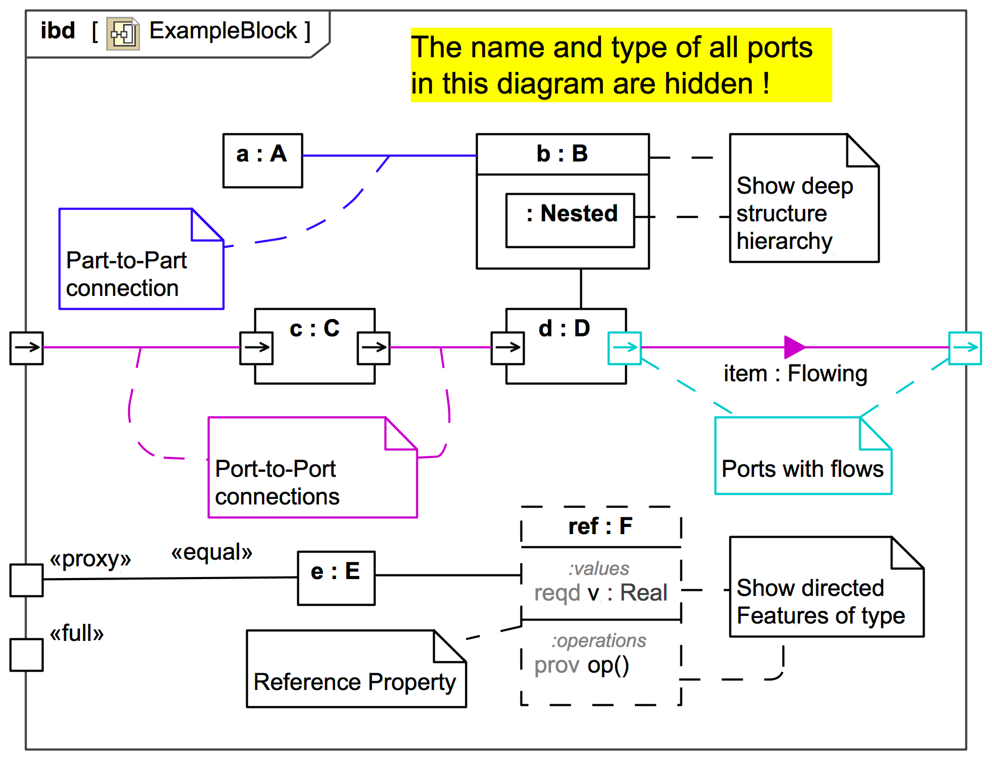
Block Diagram Rules
https://www.webel.com.au/sites/default/files/media/slide/1844/ExampleBlock.png

https://www.circuitdiagram.co › block-and …
A block and schematic diagram is a pictorial representation of a system or process that is used to help electrical engineers design and explain circuits and systems Block diagrams show the components and connections
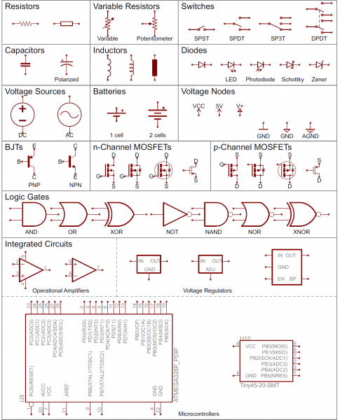
https://schempro.com › block-diagram-vs-…
The main difference between a block diagram and a schematic diagram is the level of detail provided A block diagram focuses on the overall structure and relationships between components while a schematic diagram provides a
Block Diagram Engineering Electrical Drawings And Schematics

Create Circuit Diagrams

How To Use Schematics On Basic Circuits

Reading Wiring Diagrams For Dummies

Electrical Schematics Training Electrical Schematic Symbols

How To Draw A Schematic Circuit Diagram

How To Draw A Schematic Circuit Diagram

System Block Diagram Maker Examples Edrawmax
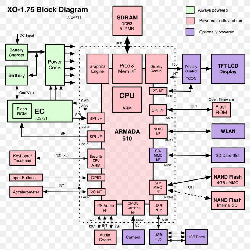
Describe Block And Schematic Diagrams Diagrams Computer Drye
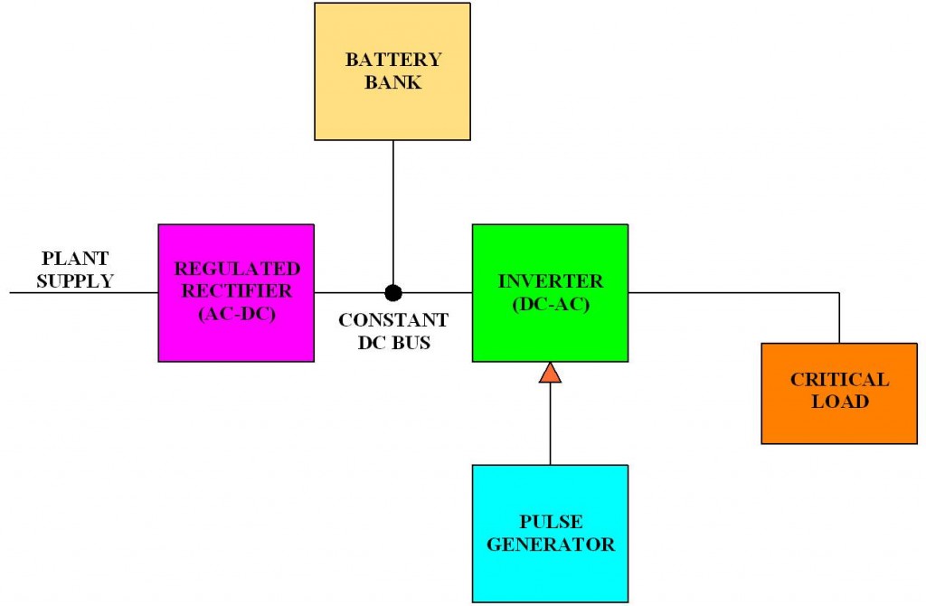
How Detailed Should Electrical Block Diagrams Basic Electric
Block And Schematic Diagrams Definition - Block Diagram A block diagram is a type of electrical drawings that represents the principle components of a complex system in the form of blocks interconnected by lines that represent their relation It is the simplest form of